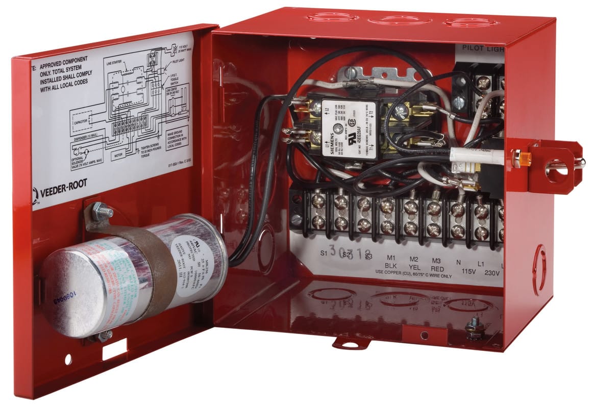
Red Jacket Control Box Wiring Diagram
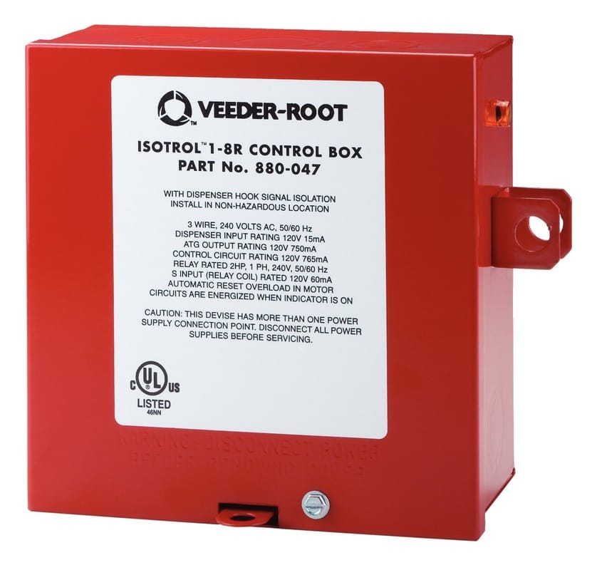
Red Jacket Isotrol 1 8 Controller Box Veeder Root

Need Wiring Diagram Verification Terry Love Plumbing Advice

3 Wire Vs 4 Wire Submersible Pump Doityourself Com Community Forums

Water Well Pressure Switch Wiring Diagram Gooddy Org New Webtor Me

Dol Starter Diagram Direct Online Starter For 3 Phase Motor

Diy Electrostatic Paint Powder Coating Oven Control Box Kit
This control box is designed to operate from 200 to 250vac.
Red jacket control box wiring diagram. The red jacket iq control box is a smart stp controller solution that provides operators with simplified pump management and unparalleled protection against downtime. Service spill elimination. The wires are the same as the orginal red jacket and we wanted to check to see if there was a compatible issue with the new box before we pulled the pump. The red jacket stp fits 4 inch npt threaded thin wall risers and is available in a wide variety of horsepowers.
Optimize your fuel flow dispensing needs setting the standard for high throughput high reliability fueling. The wiring diagram identifies the electrical terminals and lists their functions. I need to find a diagram or person who knows what sorta cap i m going to need when building my own control box. Control box is required with 3 wire single phase units.
The red jacket dealer said the replacement centripro would replace the orginal. The wires from the pressure switch connect to the electrical input terminals usually called l1 and l2 the wires heading to the well s pump motor connect to terminals with a start run. The units are designed to operate continuousl y at or above minimum flow rate or with an intermittent duty cycle not to exceed 20 on off cycles per hour. Red jacket s iq control box raises the standard for typical relay control boxes.
In this video chris shows you how to wire the franklin electric qd control box. The red jacket submersible turbine pump stp is engineered for advanced environmental protection serviceability safety and flow. The standard control box interfaces between the fuel dispenser and the turbine pump and has an indicator light that signals when a customer begins fueling. Red jacket 1 2 hp 208 230 volt 60hz 11h 7 2a code l 50n1 3450 rpm pt 179 314 3 wire there s no control box in the garage where the wires terminate.
We thought if the pump was bad it would blow the fuse before the control box but that must not be the case. Three phase motors require a magnetic starter with class 10 overload protection. Newly designed features of the red jacket stp are. Centripro 4 single phase motors red jacket type hp volts length weight no.
Inspect the control box s wiring diagram located on the back of the lid. Never wire a submersible pump to run continuously at less than minimum flow rate. Maintain safe reliable efficient fuel flow with red jacket s most basic submersible turbine pump interface. Kg 50c201 5 115 11 0 279 19 2 8 7 50c211 2 wire 5 230 11 0 279 19 2 8 7 75c211 psc.
All 3 wire submersible pumps from 1 3 up to 1 hp utilize a qd control box to start the pump. While viewing the wiring diagram figure 1 or inside the enclosure lid connect the input power l1 and l2 wires to the terminal block labeled tb1. If there was one it was cut out.
Https Www Northerntool Com Images Downloads Manuals 141456 Pdf

Unique Wiring Diagram For American Standard Gas Furnace Diagram

Submersible Well Pump Wiring Diagrams Lovetoknow
Wiring Diagram For 1998 Mercury 9 9el Page 1 Iboats Boating

Access Control Cables And Wiring Diagram Kisi
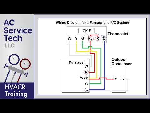
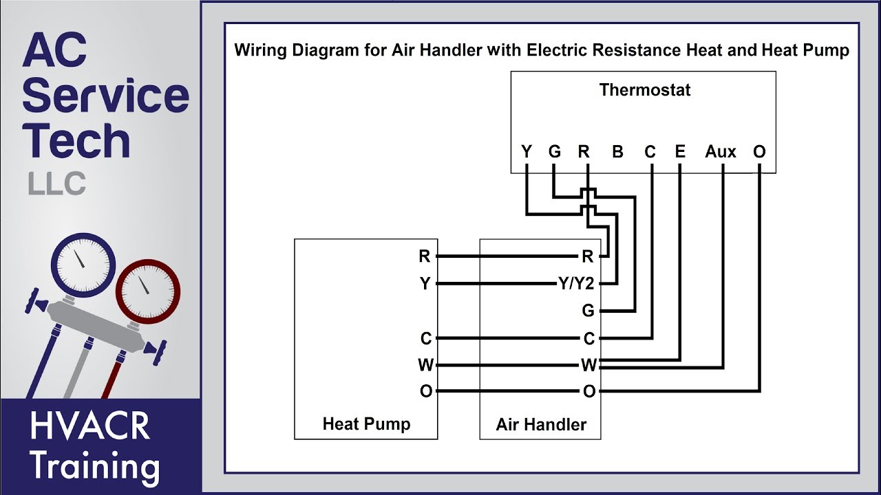
Thermostat Wiring To A Furnace And Ac Unit Color Code How It
The Red Jacket Stp Platform Veeder Root

Access Control Cabling Tutorial

2 Wire Vs 3 Wire Well Pump Motors Youtube

Meyer Snow Plow Parts Diagram Meyer Wiring Diagram Meyer Snow

Heat Wiring An Spdt Thermostat To Simultaneously Control Heating
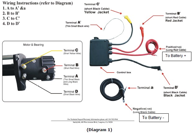
How To Install Smittybilt Gen2 X2o 17 500 Lb Winch On Your

Wiring Diagram L98 Engine 1985 1991 Gfcv Tech Bentley